Hardware Overview
The Reflex is 134 mm long, 62.5 mm wide, and 15 mm high. It is made of nickel-plated aluminium which serves as a heat sink. The bottom has four tapped mounting holes of size M4. Its detailed drawings are given in the image below.

Note: All dimensions are in mm.
Power Input
The Reflex needs to be supplied with 5 V through either of its power inputs. It can consume up to 3 A, depending on the devices connected to it. Both inputs are protected against reverse polarity and overvoltage up to 20 V.
Two additional pins on each power connector are analog inputs used for battery monitoring. The voltage on these pins should be in the range from 0 to 5 V and are measured by a 12-bit ADC. The values are scaled by a factor to obtain the battery voltage and current.
When power is available on both inputs, only one will be used. It will automatically and seamlessly switch over to the other input when necessary.
Built-in sensors
The Reflex has three IMUs built-in:
In addition, it contains a barometer for rough height estimation:
Connectivity
WiFi
The Reflex has a built-in 2.4 GHz WiFi module with external antenna support, which acts as both a WiFi access point and WiFi client. See Connecting to the Reflex for more information.
USB
The USB port is exposed through a JST-GH-5 connector. This is a USB 2.0 high speed (480 Mbps) port, and can be used for sensors, telemetry module, (mobile) internet adapter, USB flash drives, etc.
Ethernet
The ethernet is exposed through a JST-GH-5 connector on the port labelled as ETH.
UART Ports
The two UART (serial) ports are exposed through JST-GH-6 connectors (See the Pinout Reference). The TX and RX pins operate at 3.3 V but are 5 V tolerant. These can be used for supported sensors and telemetry modules.
GNSS Port
There is an additional port which is dedicated solely for GNSS use. It uses a UART communication protocol but is exposed through a JST-GH-5 (See the Pinout Reference) connector suitable for a GNSS connection. As such, the GNSS port is uniquely labeled and separated from the other, more general use UART ports.
I²C Busses
The two I²C buses are exposed through JST-GH-4 connectors (See the Pinout Reference). These can be used for supported I²C sensors.
The SDA and SCL pins operate at 3.3 V but are 5 V tolerant. Both of these pins have an internal 4.7 kΩ pull-up resistor to 3.3 V.
CAN Bus
The Reflex has two CAN ports exposed through JST-GH-4 connectors (See the Pinout Reference). While it does have internal termination, it still requires standard termination at the other end of the bus away from the Reflex. This is in the form of a 120 Ω resistor soldered between the CAN_H and CAN_L wires.
ESCs/PWM/GPIO
Up to 16 ESCs can be connected to the Reflex through the two connectors (See the Pinout Reference). The ESC pins operate at 3.3 V but are 5 V tolerant. Currently, the Reflex supports DShot (DShot600), Bidirectional DShot and PWM.
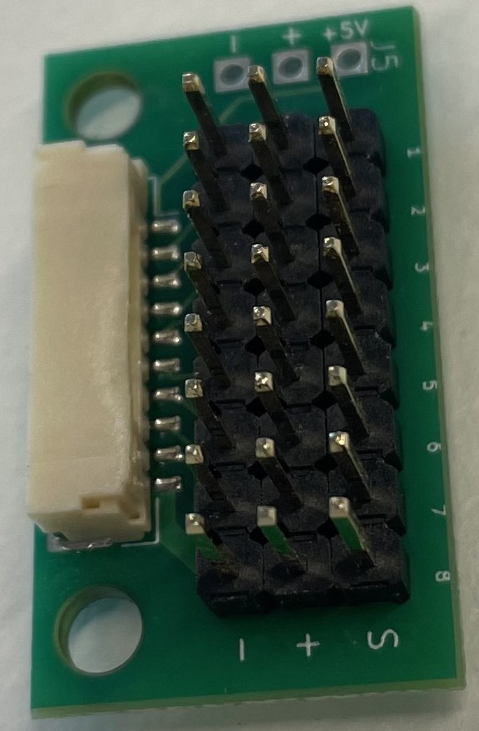
The Reflex is shipped with break-out boards to split the JST-GH-10 ESC connectors into regular 2.54 mm pin headers.
Remote Control
A remote control receiver which supports SBUS protocol can be connected to the Reflex using the dedicated RC port (See the Pinout Reference). The remote control pins operate at 3.3 V but are 5 V tolerant.
Most modern remote controllers support this protocol. Support for additional features such as a second receiver, RC protocols with telemetry (FPort, Smartport), and more will be made available through future software updates. If you are interested in these features, please contact us.