
Reflex User Manual
Version: 1.2
Last Updated: 22 December 2023
Reflex software version: v2023.04
Revision History
Version 1.2
Released on 22 Dec 2023.
Changed
- Simplified the sensor configuration procedure for rangefinder and magnetometer.
Version 1.1
Released on 8 Dec 2023.
Added
- Support for PWM ESCs.
Fixed
- Fixed error in Power LED color coding during boot.
Version 1.0
- Initial Release
IMPORTANT - Please read this disclaimer and warning carefully prior to using the Reflex flight controller. Should you have any questions, please contact us for support. By using the Reflex you, the user, acknowledge that you have read, understood and agree to this disclaimer. You agree that you are solely responsible for your conduct while using the Reflex, and for any direct or indirect consequences that may result from its use. You agree to only use the Reflex for proper purposes that are in accordance with local and airspace rules and regulations.
- The Reflex is a sophisticated flight controller and should be operated with extreme care, as improper operation can cause damage to property, serious personal injury or death.
- Always check the Reflex and its peripherals prior to operation.
- Always fly the drone with the Reflex in accordance with local as well as airspace rules and regulations.
- Always remove the propellers, or the power to the ESCs, when making changes to the configuration to prevent propeller strikes in the event of unintentional motor starts.
- Always test the Reflex with the propellers removed to ensure that the motors are spinning in the correct direction and that the motor assignment is correct. If either of these are incorrect, the drone may be uncontrollable and dangerous.
- It is the user's responsibility to perform a full system check of the Reflex prior to every flight.
- It is the user's responsibility to make sure the Reflex is properly configured and tuned before use.
- Always maintain a safe distance from the drone when in use.
- Never attempt to touch the drone or its components when the propellers are moving.
Abbreviations
| Abbreviation | Definition |
|---|---|
| ADC | Analog-to-digital Converter |
| BEC | Battery Eliminator Circuit |
| CAN | Controller Area Network |
| ESC | Electronic Speed Controller |
| I²C | Inter-Integrated Circuit |
| IMU | Inertial Measurement Unit |
| INDI | Incremental Nonlinear Dynamic Inversion |
| IO | Input/Output |
| GCS | Ground Control Station |
| GNSS | Global Navigation Satellite System |
| GPIO | General-Purpose Input/Output |
| LiPo | Lithium Polymer |
| PDB | Power Distribution Board |
| PID | Proportional-Integral-Derivative |
| PPS | Pulse Per Second |
| PWM | Pulse Width Modulation |
| RAM | Random Access Memory |
| RC | Remote Controller |
| RTL | Return to Launch |
| SCL | Serial Clock |
| SDA | Serial Data |
| UART | Universal Asynchronous Receiver/Transmitter |
| UKF | Unscented Kalman Filter |
| USB | Universal Serial Bus |
Introduction
Fusion Engineering's flagship flight controller, the Fusion Reflex, introduces a new era of drone flight capabilities. Its lightweight aluminium build and powerful hardware make it an impressive piece of technology. But its true strength lies in its adaptable software.
Developed entirely from scratch using Rust as the programming language and incorporating the latest research, the Reflex boasts unparalleled reliability and flexibility. The Fusion Reflex is poised to meet the needs of the next generation of commercial drone applications.
Reflex Package Contents
The Reflex package comes with the flight controller as well as other parts such as the cables needed and ESC breakout boards. A comprehensive list of the contents is given below:
- Reflex flight controller
- WiFi Antenna + adapter
- Power cable – USB to Molex
- USB Power adapter
- Molex nano fit power cable (2 units)
- JST GH 5 to USB - Cable
- JST GH 5 to USB socket - Dongle
- Ethernet RJ45 socket to JST-GH 5 adapter
- JST-GH 4 pin pre-crimped cable (4 units)
- JST-GH 5 pin pre-crimped cable (2 units)
- JST-GH 6 pin pre-crimped cable (2 units)
- JST-GH 10 pin pre-crimped cable (2 units)
- ESC signal breakout board (2 units)
- Extra pre-crimped wires and JST-GH connectors (4,5,6 and 10 pin)
Product Overview
The Fusion Reflex comes with many adaptable features. In order to better understand the product, its various components are explained in the following sections.
Hardware
An overview of the physical properties of the Reflex can be seen in the table given below. Further details are also available under Hardware Overview.
| Characteristics | Value |
|---|---|
| Length | 134 mm |
| Width | 62.5 mm |
| Height | 15 mm |
| Mounting hole screw size | M4 |
| Weight | 130 g |
Connectivity
Unless otherwise specified, all I/O uses 3.3 V output, and accepts both 3.3 V and 5 V input.
- Two independent I²C buses
- Two independent UART/serial ports
- One GNSS UART port with an additional Pulse Per Second (PPS) pin
- Two CAN ports
- USB OTG
- Four analog inputs (0-5 V), two per redundant power input
- Two sets of eight I/O pins for ESCs/PWM/GPIO, supporting bidirectional DShot
- Dedicated RC port which supports SBUS and an option to support DSM, S.Port, or F.Port
- Built-in 2.4GHz and 5 GHz WiFi with an external antenna
- 10/100 Ethernet port
Sensors
Triple redundant IMUs and barometer
- Three TDK ICM-42688P accelerometer and gyroscope
- BMP390 barometer
Power input
- Two 5 V redundant power inputs
Processors and memory
- 1.5 GHz 64-bit ARM Cortex A72 processor with four cores
- 2 GiB RAM
- 32 GiB flash storage
- Separate 100 MHz ARM Cortex-M4 processor for I/O signals and ESC RPM control
Control
- Non-linear control based on INDI for superior performance in extreme situations.
- Flexible drone layout with the ability to configure any number of rotors in any position and orientation.
- Fault detection and fault-tolerant control, allowing the drone to fly even with damaged ESCs/motors on selected frames.
- Advanced state estimation based on Unscented Kalman Filtering.
- Dual GNSS heading support.
- Sensor redundancies.
- Smoother stick controlled flights.
- Advanced sensor filtering to remove noise and improve data accuracy and reliability.
Software
- Modular and reliable software framework with tasks running in isolated processes.
- Flexible sensor layer that can support any number and type of sensors, limited only by bus bandwidth.
- Efficient and extensive custom data logging framework with CSV export.
- Communication facilitated through MAVLink.
- Overall system and sensor health monitoring.
Hardware Overview
The Reflex is 134 mm long, 62.5 mm wide, and 15 mm high. It is made of nickel-plated aluminium which serves as a heat sink. The bottom has four tapped mounting holes of size M4. Its detailed drawings are given in the image below.

Note: All dimensions are in mm.
Power Input
The Reflex needs to be supplied with 5 V through either of its power inputs. It can consume up to 3 A, depending on the devices connected to it. Both inputs are protected against reverse polarity and overvoltage up to 20 V.
Two additional pins on each power connector are analog inputs used for battery monitoring. The voltage on these pins should be in the range from 0 to 5 V and are measured by a 12-bit ADC. The values are scaled by a factor to obtain the battery voltage and current.
When power is available on both inputs, only one will be used. It will automatically and seamlessly switch over to the other input when necessary.
Built-in sensors
The Reflex has three IMUs built-in:
In addition, it contains a barometer for rough height estimation:
Connectivity
WiFi
The Reflex has a built-in 2.4 GHz WiFi module with external antenna support, which acts as both a WiFi access point and WiFi client. See Connecting to the Reflex for more information.
USB
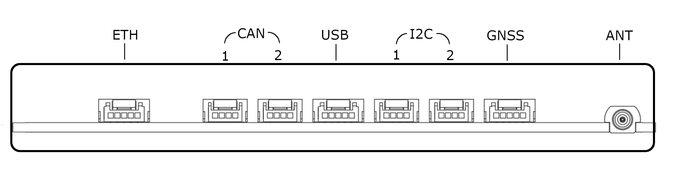
The USB port is exposed through a JST-GH-5 connector. This is a USB 2.0 high speed (480 Mbps) port, and can be used for sensors, telemetry module, (mobile) internet adapter, USB flash drives, etc.
Ethernet
The ethernet is exposed through a JST-GH-5 connector on the port labelled as ETH.
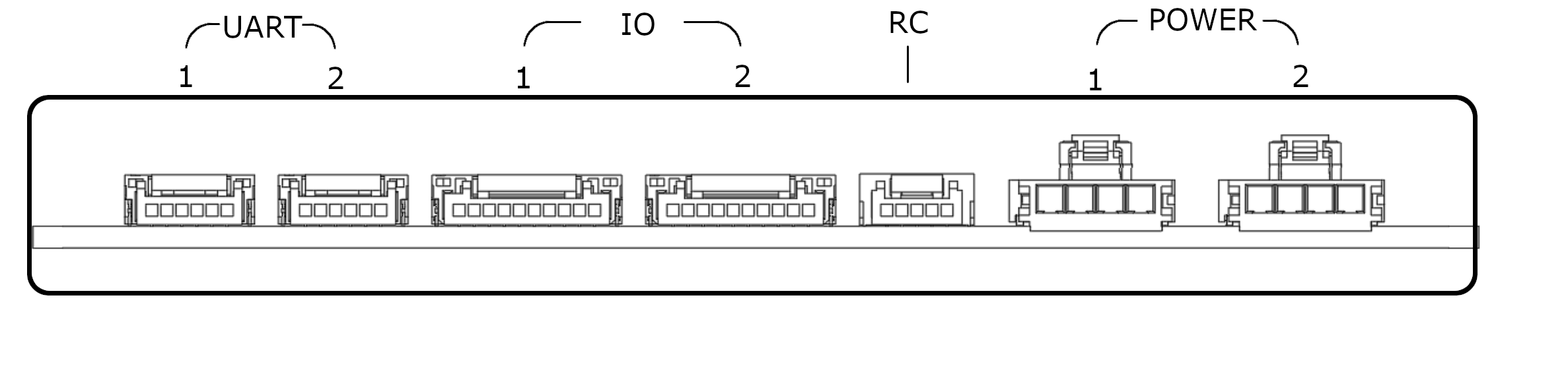
UART Ports
The two UART (serial) ports are exposed through JST-GH-6 connectors (See the Pinout Reference). The TX and RX pins operate at 3.3 V but are 5 V tolerant. These can be used for supported sensors and telemetry modules.
GNSS Port
There is an additional port which is dedicated solely for GNSS use. It uses a UART communication protocol but is exposed through a JST-GH-5 (See the Pinout Reference) connector suitable for a GNSS connection. As such, the GNSS port is uniquely labeled and separated from the other, more general use UART ports.
I²C Busses
The two I²C buses are exposed through JST-GH-4 connectors (See the Pinout Reference). These can be used for supported I²C sensors.
The SDA and SCL pins operate at 3.3 V but are 5 V tolerant. Both of these pins have an internal 4.7 kΩ pull-up resistor to 3.3 V.
CAN Bus
The Reflex has two CAN ports exposed through JST-GH-4 connectors (See the Pinout Reference). While it does have internal termination, it still requires standard termination at the other end of the bus away from the Reflex. This is in the form of a 120 Ω resistor soldered between the CAN_H and CAN_L wires.
ESCs/PWM/GPIO
Up to 16 ESCs can be connected to the Reflex through the two connectors (See the Pinout Reference). The ESC pins operate at 3.3 V but are 5 V tolerant. Currently, the Reflex supports DShot (DShot600), Bidirectional DShot and PWM.
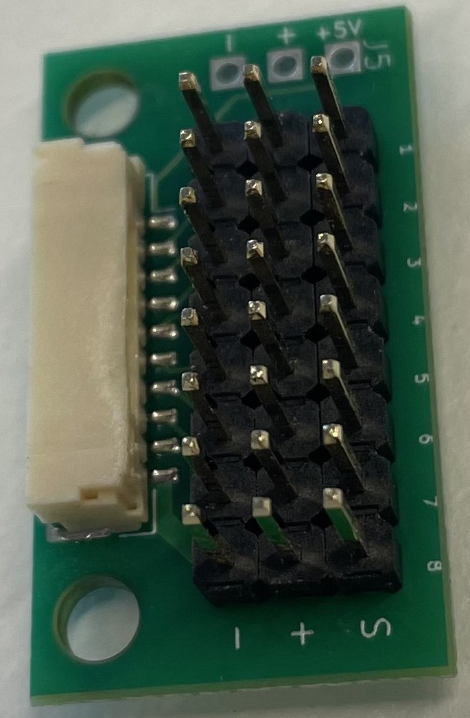
The Reflex is shipped with break-out boards to split the JST-GH-10 ESC connectors into regular 2.54 mm pin headers.
Remote Control
A remote control receiver which supports SBUS protocol can be connected to the Reflex using the dedicated RC port (See the Pinout Reference). The remote control pins operate at 3.3 V but are 5 V tolerant.
Most modern remote controllers support this protocol. Support for additional features such as a second receiver, RC protocols with telemetry (FPort, Smartport), and more will be made available through future software updates. If you are interested in these features, please contact us.
Pinout Reference
UART 1JST-GH-6
|
ETHJST-GH-5 |
Reflex Features
The Reflex offers various essential features for safe and effective flight operations, and new features are continuously developed and released through incremental updates. These include flight modes (piloted as well as autonomous), flight assist features, and flight safety features. If you have a request for a specific feature, please don't hesitate to contact us.
Control Algorithms
The Reflex offers two control algorithms: INDI (requires motor RPM feedback) and PID. This redundancy in control architecture ensures enhanced reliability and stability during flight operations.
Piloted Flight Modes
The Reflex supports three remote-controlled, or piloted, flight modes: Attitude Mode, Altitude Mode, and Position Mode. Of these, attitude mode provides the highest degree of manual control, while position mode is the most assisted flight mode. The stick inputs as well as their corresponding responses in each mode are detailed in the tables below.
Attitude Mode
| RC Channels | Command |
|---|---|
| roll | Desired roll angle of the drone |
| pitch | Desired pitch angle of the drone |
| yaw | Desired yaw rate of the drone |
| throttle | Desired throttle value, where the drone climbs if the value is greater than hover throttle |
Altitude Mode
| RC Channels | Command |
|---|---|
| roll | Desired roll angle of the drone |
| pitch | Desired pitch angle of the drone |
| yaw | Desired yaw rate of the drone |
| throttle | Desired upwards speed of the drone with altitude hold when stick is central |
Position Mode
| RC Channels | Command |
|---|---|
| roll | Desired lateral speed in roll direction with position hold when stick is central |
| pitch | Desired lateral speed in pitch direction with position hold when stick is central |
| yaw | Desired yaw rate with heading hold when stick is central |
| throttle | Desired upwards speed of the drone with altitude hold when stick is central |
Automated Flight Modes
The Reflex provides several automated modes that do not require the pilot to actively control the sticks. These automated modes and their functions are provided below.
-
Mission Mode: This is an autonomous flight mode that adheres to a pre-defined mission path, typically consisting of a series of waypoints and/or maneuvers.
-
Land Mode: This mode initiates a vertical descent of the drone at the location where the mode was activated and allows the drone to land from there.
-
Takeoff Mode: This mode initiates a vertical ascent at the current location to a predefined takeoff altitude relative to the home location while maintaining its lateral position. It holds its position after reaching the takeoff altitude.
-
Return to Launch Mode: This mode commands the drone to fly back to its home location and land, following a path defined by the user's configuration.
Flight Assist Features
These are features which were implemented to assist the pilot with controls during various flight stages such as landing, takeoff, hover, etc.
-
Bank Angle Protection: Bank angle protection is a feature that helps prevent a drone from rolling or tilting too far to one side during flight very close to ground. It works by limiting the maximum angle at which the drone can bank as a function of height above ground, in order to prevent the drone from entering a potentially dangerous or unstable flight state.
-
Takeoff and Landing Detector: This feature enables the drone to detect when it has taken off and landed, allowing it to automatically disarm after landing or if it fails to take off after arming.
-
Terrain Hold: The terrain hold feature allows the drone to maintain a constant altitude above the ground when holding in Position, Hold, and Takeoff modes.
Safety Features
These are a list of features on the Reflex that are executed as a safety precaution in case of situations which may potentially cause harm or damage to the drone or others.
-
Remote Control Loss: The RC loss feature is a safety mechanism that helps prevent the drone from flying out of control in the event of a lost connection between the drone and the remote controller (RC). When this feature is activated, the drone will automatically execute a pre-defined emergency procedure as configured by the user.
-
Battery Low: The low battery safety feature allows the drone to automatically execute an emergency procedure when the battery level drops to a critically low level.
-
Sensor Loss: The Reflex is designed to handle in-flight sensor loss by automatically switching flight modes based on available sensors.
-
Takeoff Attitude Protection: Takeoff attitude protection is a safety mechanism that shuts down the drone automatically if it senses excessive bank angles immediately before takeoff. This may suggest that the motors are connected in the wrong configuration, causing it to rotate in the opposite direction.
-
Geofence: The geofence is a safety feature that prevents the drone from flying into dangerous or restricted airspace by defining a virtual boundary. At present, the Reflex permits the use of a cylindrical geofence centred around the home location.
Supported Frames
The Reflex drone is designed to support a wide variety of multirotor configurations with up to 16 motors, as long as the motors are arranged along a plane. This includes common configurations like quadcopters, hexacopters, and octocopters, as well as less common configurations that use coaxial motors.
Fusion Engineering is able to provide support for custom frames based on specific use-cases. For more information on this service, please don't hesitate to contact us.
Supported sensors
Sensors currently supported are:
Magnetometer
PNI RM3100 (I²C)
InvenSense MPU-9250 (I²C)
GNSS
u-blox NEO-M8P and ZED-F9P modules
Telemetry
Telemetry systems supporting serial port protocol
Rangefinder
Garmin Lidar lite v3 (I²C)
Benewake TFmini-s (I²C)
Nanoradar NRA24 (UART)
Optical Flow
PX4Flow (I²C)
The Reflex is regularly updated with support for new sensors in response to user demand. For requests regarding support of other sensors, please contact us.
ESC Protocol
The Reflex drone supports Electronic Speed Controllers (ESC) that are capable of communicating through (Bidirectional) DShot protocol.
DShot
DShot is a digital ESC protocol, providing advantages over analog protocols like PWM, OneShot and MultiShot:
- No calibration needed, resulting in increased robustness to noise and signal frequency.
- High-frequency RPM telemetry over the dataline is supported.
- Motor reversing can be achieved without the need for (de)soldering.
The Reflex currently supports the DShot600 protocol.
Bidirectional DShot
Bidirectional DShot enables the ESC to send high-frequency speed telemetry back to the flight controller through the dataline.
While the Reflex does fly using the regular DShot protocol, in order to use the latest innovative features such as the INDI controller, it is recommended to use ESCs supporting Bidirectional DShot.
PWM Protocol
The Reflex also offers support for ESCs utilizing PWM (Pulse Width Modulation) with PWM frequencies ranging from 50 to 500Hz.
Supported DShot Hardware
BLHeli ESC
ESCs running BLHeli_32 firmware are shipped running Bidirectional DShot firmware out of the box. If possible, the use of a BLHeli_32 ESC is advised. These are plug-n-play compatible with the latest innovative features on the Reflex. ESC settings can be configured using the BLHeliSuite32 configurator.
ESCs running BLHeli_S firmware come shipped with the regular DShot protocol. It is possible to get Bidirectional DShot working on that hardware, but flashing of different firmware is needed.
At the time of writing this documentation, two different firmwares for BLHeli_S ESC's are known to be capable of running Bidirectional DShot:
KISS ESC
KISS ESCs are developed by Flyduino and are capable of running Bidirectional Dshot. Protocol settings can be changed in the chrome application KISS GUI.
APD F-series ESC
Advanced Power Drives (APD) is an Australian company, developing ESCs for high power applications. The F-series has ESCs rated for 6S, 8S, 12S and 14S voltages.
All F-series ESCs support regular DShot straight out of the box.The F-series 80F3v2 rated for 8S and 120F3v2 rated for 12S come shipped with Bidirectional Dshot. The F-series 40F3 rated for 6S can be flashed with firmware that supports Bidirectional Dshot. The 200F3v2 does not allow for Bidrectional Dshot.
Check their documentation for a guide on uploading the correct firmware onto the ESCs.
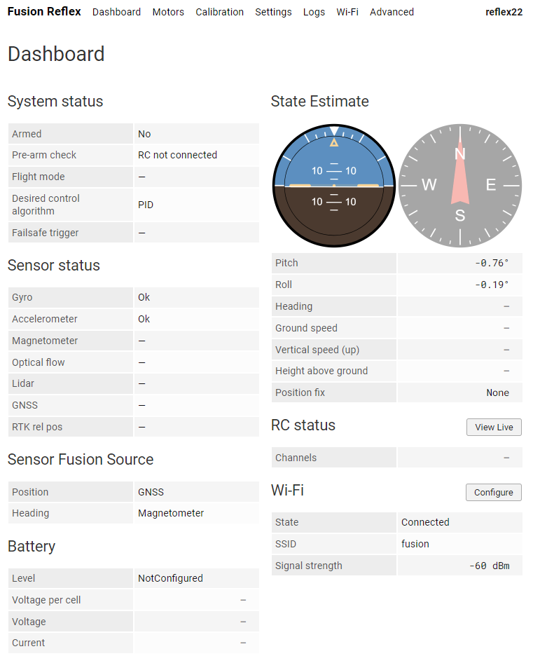
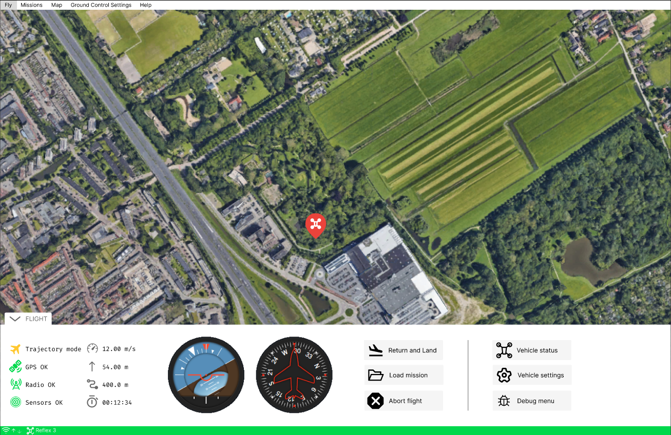
Web Interface
The Reflex can be monitored and configured using a user-friendly web interface that can be accessed through a Wi-Fi connection. This interface provides real-time information about the drone's state and allows users to adjust various settings to optimize performance. Through the web interface, users can also access advanced features and fine-tune the drone's behavior to suit specific use cases. Given below is an example of how the web interface's Dashboard page appears.
Fusion Ground Control Station
The custom-built ground control station (GCS) by Fusion Engineering supports MAVLink messages over telemetry or User Datagram Protocol (UDP), but the Reflex also supports other ground control stations that use the same protocol. Communication between the Reflex and GCS is facilitated through MAVLink messages, which ensures efficient and reliable data transfer. Regardless of the GCS being used, the Reflex drone is designed to enable seamless communication and reliable operation for a safer and more effective flight experience.
Currently the Fusion GCS is designed to complement the Web Interface. Support to new MAVlink messages is constantly being added.
Getting Started
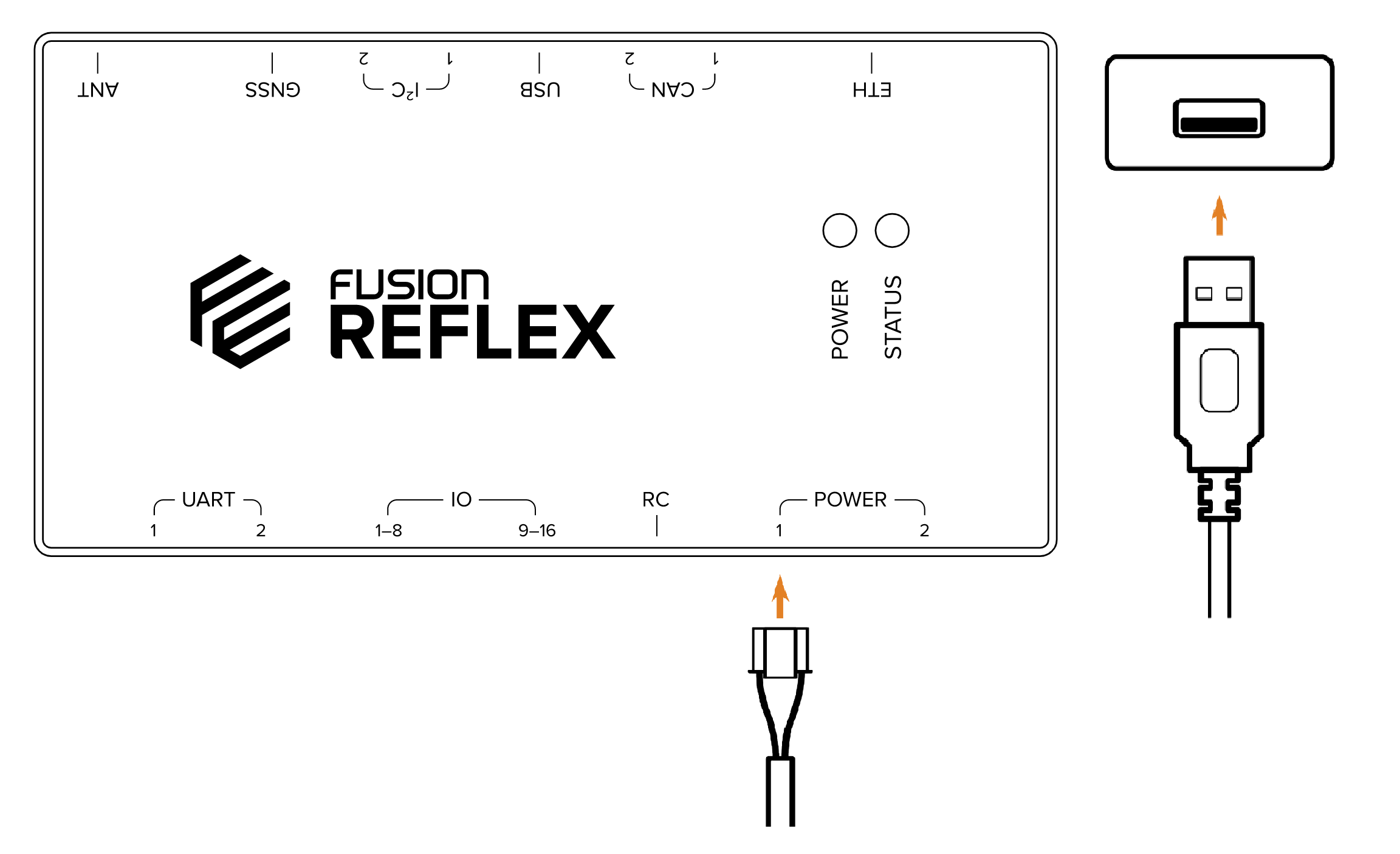
As mentioned in the Reflex Package Contents section, the box in which the Reflex is shipped contains a power cable and a USB power adapter. These can be used to power the Reflex, using either of its power ports.
No other cables are necessary for the first time set-up since the Reflex can be connected to wirelessly once powered on. This process will be elaborated on in the section, Connecting to the Reflex.
When powered on, the Power LED will show a solid red light to indicate that the Reflex is booting. Once the booting process is complete, the Power LED will turn to green indicating that the Reflex is ready to use. The rest of this chapter will explain the steps that need to be followed after this to confirm basic functionality of the Reflex.
Connecting to The Reflex
To begin configuring the Reflex, an interface is provided which can be accessed through a web browser without any additional software. There are two ways to establish a connection between the Reflex and a computer: direct connection or the local WiFi network.
Direct Connection
The Reflex can always be accessed directly, regardless of the availability of a WiFi network or its configuration. It provides a dedicated network named "reflex" followed by its serial number, such as "reflex123". The default password is included in the original box.
To access the Reflex's web interface, simply connect to the network and enter http://10.120.1.1/ in a web browser. This direct connection method is always available, but does not provide internet connectivity to the Reflex.
Local WiFi Network
The Reflex can also be connected to a local WiFi network. This provides internet access to the Reflex and allows the user's computer to remain connected to the internet while still accessing the Reflex.
Note: This method of establishing a connection is currently not possible but will be made available via a future software update.
COnnecting to the internet
The Reflex can currently access the internet using the provided Ethernet RJ45 socket to JST-GH adapter.
IMU Calibration
The Reflex has three built in Inertial Measurement Units (IMU) used for measuring the triaxial accelarations as well as angular velocities. The model used on the Reflex is the InvenSense ICM-42688P which consists of both an accelerometer and a gyroscope. The calibration of these sensors is easiest done prior to mounting the Reflex on the drone and so, must be done first.
Accelerometer calibration
The accelerometers must be calibrated prior to mounting. Calibration can be started on the web interface by navigating to:
Web Interface: Calibration > Accelerometer
After clicking the Start Calibration button, put the Reflex on a flat surface and wait for the displayed bin to fill to 100%. Repeat for each side of the Reflex. After all bins are filled, calibration is completed.
Gyroscope calibration
The gyroscope calibrates at startup. For it to successfully calibrate, the drone needs to be standing still (see the Standing Still flag on the Dashboard).
Status of the gyroscope calibration can be monitored in the Gyro entry of the Sensor Status part of the Dashboard. When the entry shows an "Ok", then the gyroscope can be considered to be calibrated.
Mounting The Reflex
While mounting the Reflex on a drone, its orientation and location upon installation must be configured. The following section details how to mount and properly configure the flight controller so that it functions correctly.
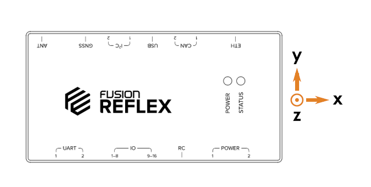
Mounting Orientation
The figure below shows the direction of the axes of the local coordinate system of the Reflex. The origin of the coordinate system is in the geometric centre of the Reflex.
The mounting orientation as well as the location of the Reflex with respect to the centre of gravity of the drone can be configured on the web interface. This is done by navigating to the relevant sections of the Settings as given below.
Web Interface: Settings > Drone > Mounting Orientation
Web Interface: Settings > Drone > Controller Position
Under Mounting Orientation, the orientation of the controller's X and Y axes can be configured in relation to the orientation of the drone. Under Controller Position, the offset of the controller's center of gravity with respect to the drone's can be inputted in terms of the X, Y and Z axes.
Vibration Damping
The Reflex houses accelerometers and gyroscopes units (IMUs) which are sensitive to vibrations from the motors and other vibrations produced by a flying drone. If the experienced vibrations are too large, the Reflex's state estimation of the drone can become inaccurate, leading to issues with the dynamic controls. The goal of vibration damping is to reduce high frequency noise from the drone while allowing the lower frequency movements (the actual flight movement of the drone) to reach the accelerometers and gyroscopes.
The preferred method for physically damping the Reflex can be different depending on the frequency of the unwanted vibrations and the motor speeds. Different mounting solutions have different filtering properties. Commonly used mounting methods are:
- Vibration damping balls
- Foam tape
- Rubber standoffs
Alternatively, the Reflex may be hardmounted to the vehicle, however it is advised that the RPM Notch Filter is configured in order to filter out noise induced by the drone's motors.
Wiring Requirements
The Reflex uses standard JST-GH connectors for most of the interfaces. The required wiring that needs to be organised prior to integrating the Reflex includes:
- Power:
- 5 V to Reflex power connection through 4 pin Molex nano-fit connector with 0 - 5 V analog voltage and current battery measurement signal.
- ESC:
- ESCs signal wiring to the Reflex's ESC port through 10 pin JST-GH connector via Fusion ESC signal breakout board.
- Sensors:
- GNSS rover module to the Reflex's 5 pin JST-GH GNSS port.
- Magnetometer to the Reflex's 4 pin JST-GH I²C port.
- Rangefinder to the Reflex's 4 pin JST-GH UART or I²C port.
- Telemetry to the Reflex's 4 pin JST-GH UART port.
- Remote Control:
- Radio receiver to the Reflex's 5 pin JST-GH port.
Power
The Reflex requires a 5 V power supply within an operating range of 4.75 V to 5.25 V. The 5 V power can be supplied to the Reflex using the provided USB power cable for ground testing. However, for drone operations, the typical method of supplying power is through a LiPo battery connected to a Power Distribution Board (PDB) on the drone. The PDB distributes power from the battery to the Electronic Speed Controllers (ESC). Some PDBs also provide a 5 V output that can be used to power the Reflex. If the PDB does not have a built-in 5 V output, an additional Battery Eliminator Circuit (BEC) would be required to supply the necessary 5 V power to the Reflex.
Commenly used PDBs are from Mateksys and Holybro.
Some PDBs are known to provide V/I measurement via analog signal. If a PDB does not have this capability, an analog power module such as Holybro PM02 V3 can be used. It should be connected inbetween battery and the PDB.
The 5 V power and analog signals are connected to the Reflex through a Molex Nanofit 4 pin connector as seen in Pinout Reference.
Note: Support for digital voltage and current measurement through I²C will be added via software update in the near future.
ESC
The Reflex supports ESCs that communicate using both (Bidirectional) DShot and PWM protocols, as detailed in ESC Protocol. The ESCs can be connected to the Reflex through the 10-pin JST-GH connector on the IO ports as seen in Pinout Reference. The IO ports support up to 16 ESCs.
The Reflex also ships with break-out boards that can be used to divide the 10-pin connector into the regular 2.54 mm pin headers that generally come with ESCs. This can also be seen in ESCs.
Sensors
The sensors on the drone can be connected to the Reflex using the UART and the I²C ports available on it. The supported sensors which use these I²C or UART communication protocols to interface with the Reflex are listed in Supported Sensors. For the required wiring and communication protocols associated with each of the specific sensors, please refer to Pinout Reference.
Remote Control
The Reflex has a 5 pin JST-GH port dedicated to an RC receiver connection. The wiring it requires can be seen in Pinout Reference based on the protocol used. For the SBUS protocol, the wire needs to be connected to the RXTX1 port of the RC.
Motor Configuration
In order for the Reflex to control the motors, their characteristics when on the drone must be defined under Settings in the web interface.
Motors
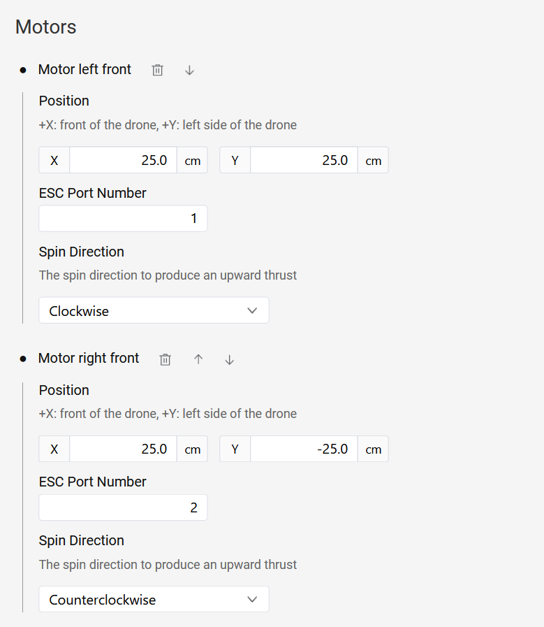
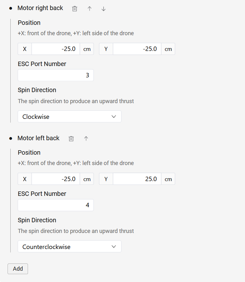
The position and rotation direction of all the motors on the drone can be configured in Settings. Motors can be added in the relevant settings page by navigating to it as demonstrated below:
Web Interface: Settings > Drone > Motors
Click the Add button to add a motor, after which you can enter the motor's x and y positions in the Reflex's coordinate frame, along with its rotation direction. The figure of a quadcopter below provides an example for the manner in which the motors can be numbered and their positions in the given coordinate system.
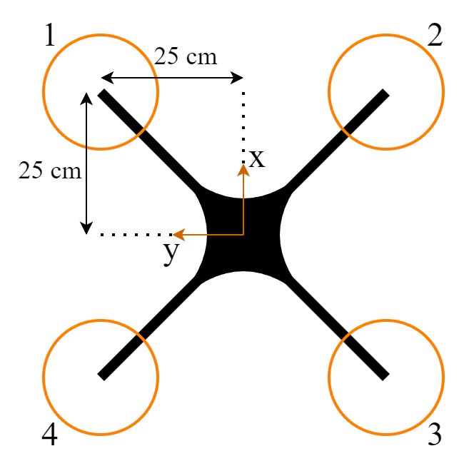
There is no specific order that needs to be followed when adding motors to the Reflex. Motor numbering starts at 1, and as many motors as necessary can be added to the settings by clicking the Add button. The Reflex currently supports drone frames with up to 16 motors.
The ESC port number should correspond to the pin number on the Reflex to which the ESC is connected (see Pinout Reference for the pin numbering). This configuration process is summarized in the images below.
ESC Protocol Configuration
The choice of ESC protocol can be configured in the following location:
Web Interface: Settings > Drone > Motor Controller > Protocol
The Reflex supports three ESC protocols, which are listed below.
Dshot
To configure DShot600 as the ESC protocol, Select the Dshot protocol in the settings.
Bidirectional Dshot
Bidirectional DShot enables the Reflex to receive motor RPM feedback. To configure the Bidirectional DShot settings, you need to specify the motor pole count. This value should be tailored to the specific motors being used, as it corresponds to the number of permanent magnets within the motor.
Motor Controller
The Motor Controller is responsible for tracking the desired RPM setpoint of each motor. This component is crucial for the functionality of the INDI control algorithm. The controller incorporates a Proportional-Integral (PI) controller and operates on each motor individually.
To begin the tuning process of this controller, it's essential to have RPM feedback through Bidirectional DShot enabled. You can initiate the tuning process using the default gains provided. Afterward, verify the tracking by analyzing RPM feedback and RPM setpoint information in the logs. If necessary, adjust the gains accordingly to optimize the performance of the Motor Controller and ensure precise RPM control for each motor.
PWM
To select PWM as the ESC protocol, please choose PWM in the settings. The user needs to specify the PWM frequency within the range of 50-490 Hz. Higher rates are generally better, but the value should depend on the maximum update rate supported by the ESCs.
The PWM ESCs require calibration so that the ESCs sync with the Reflex for low and high values. The procedure can be found in the PWM ESC Calibration page.
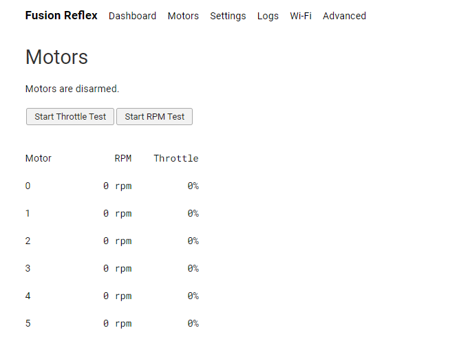
Motor Test
The motor test page in the web-interface allows the user to validate the proper functioning and spin direction of each of the motors. This page can be found in the navigation bar of the web-interface under Motors. The user can control the throttle or the rpm of the motors (if Bidirectional DShot is enabled and motor controller is configured)
For safety reasons, please make sure all propellers are removed prior to beginning the test.
Clicking the Start Throttle Test or Start RPM Test arms the motors for a manual motor test.
The motors can be controlled individually or all together via sliders. If Bidirectional DShot is enabled, the RPM is displayed as well. Check the image below for an overview of the motors tab in the web interface:
PWM ESC Calibration
In order to perform calibration of PWM ESCs, follow these steps:
- Remove the propellers.
- Disconnect the ESCs from the power source while keeping the Reflex powered on.
- Configure the minimum and maximum throttle to 0% and 100% in the settings below:
Web Interface: Settings > Drone > Motor Controller > Output Throttle Range
- Navigate to the Motor Test page and select Start Throttle Test.
- Set the throttle for all the ESCs to 100% by moving the slider all the way to the end.
- Power on the ESCs. They should enter calibration mode and continue to beep while recording the maximum throttle.
- Once the beeping stops, set the throttle for all the ESCs to 0% by moving the slider on the motor test page.
- The ESCs will beep and record the minimum throttle.
- Once this is done, the ESCs' calibration is complete.
Warning: Ensure that the propellers are removed before initiating the PWM calibration.
Note: During the calibration process, the motors should not be spinning. If a motor spins, please double-check that you have followed the instructions correctly.
Remote Control
The Reflex currently supports the SBUS protocol, so it is advised to use a remote controller that is compatible with SBUS. For example, the RC brands of FrSky and Futaba are commonly known to support SBUS.
Note: Support to other RC protocols will be added via software update in near future.
Channels
The default mappings are as follows:
- Roll : Channel 1,
- Pitch : Channel 2,
- Throttle : Channel 3,
- Yaw : Channel 4,
- Flight Mode Switch 1 (3-way switch) : Channel 5,
- Low (Negative): Attitude mode.
- Centre (Zero): Altitude mode.
- High (Positive): Position mode.
- Flight Mode Switch 2 (3-way switch) : Channel 6,
- Low (Negative): Not assigned.
- Centre (Zero): Not assigned.
- High (Positive): Mission mode.
- Arm/Disarm : Channel 7,
- Kill : Channel 8,
- Control Algorithm : Channel 9,
The live status of the remote control data can be seen in the web interface, by clicking View Live next to RC status on the dashboard.
Sensor Configuration
The Reflex supports several peripheral sensors that are mentioned in Supported Sensors section. The processes to configure these sensors is explained in the following subsections:
GNSS sensors
Reflex supports GNSS modules speaking UBX protocol over UART/USB, specifically the u-blox NEO-M8P and ZED-F9P modules. There is a dedicated UART port for GNSS on the Reflex with an extra pin for a pulse per second (PPS) signal as mentioned in Product Overview.
GNSS Configuration
In order to configure the Rover GNSS module, you must specify which port it is connected to which can be done by navigating to the relevant page as seen below.
Web Interface: Settings > Sensors > GNSS
Note: Make sure to reboot the Reflex after the sensor is configured. This allows the new settings to take effect for further use.
Once connected, the Reflex automatically configures the Rover GNSS module to send NAV-PVT and NAV-RELPOSNED messages at a specific update rate.
If you are using an RTK setup, the base GNSS module has to be configured using external software such as u-blox u-center. The procedure for it can be found in GNSS Configuration page.
GNSS Monitoring
GNSS status can be viewed in the dashboard as follows:
Web Interface: Dashboard > Sensor Status > GNSS
Raw GNSS data can be viewed in the live data viewer as follows:
Web Interface: Advanced > Raw Data > Inspect Raw Data > sensors/gnss
Magnetometer
This section provides information on the configuration and calibration of the following sensors:
| Sensor |
|---|
| PNI RM3100 (I²C) |
| AKM AK8963 (I²C) |
Configuration
To configure the magnetometer sensor, select the sensor name, the port to which it is connected, and the orientation of the sensor with respect to the drone in the following settings.
Web Interface: Settings > Sensors > Magnetometer
Note: Make sure to reboot the Reflex after the sensor is configured. This allows the new settings to take effect for further use.
After the sensor has been configured, the raw data from the magneto sensor can be found at:
Web Interface: Advanced > Raw Data > Inspect Raw Data > sensors/magneto
Calibration
Before use, the magnetometer needs to be calibrated. This calibration should be done after the magnetometer is mounted on the drone, outdoors, with as little amount of interference as possible (away from buildings, metal surfaces, etc.) to account for the current local magnetic field. The magnetometer calibration procedure is started by
Web Interface: Calibration > Magnetometer
Once started, the drone, along with the Reflex, has to be rotated completely about all three axes until all calibration bins reach 100%.
Rangefinders
The Reflex currently supports the following rangefinder sensors.
| Sensor |
|---|
| Garmin Lidar Lite v3 (I²C) |
| TFmini-s (I²C) |
| Lightware SF11/ SF20/ LW20/ SF000 (I²C) |
To configure the rangefinder sensor, select the sensor name and the port to which it is connected in the following settings. Please select SF11 if you are using one of the Lightwear lidars.
Web Interface: Settings > Sensors > Range Finder
Note: Make sure to reboot the Reflex after the sensor is configured. This allows the new settings to take effect for further use.
After the sensor has been configured, the raw data from the sensor can be found at
Web Interface: Advanced > Raw Data > Inspect Raw Data > sensors/distance
Telemetry
The Reflex currently supports communication with other devices through MAVLink messages sent over the UART serial protocol and UDP.
Connection over Serial
In order to configure the telemetry receiver module, the user must select the Serial Port by navigating to the GCS Connection as given below. The user must then specify which UART port it is connected to and the baud rate at which it communicates.
Web Interface: Settings > MAVlink > GCS Connection
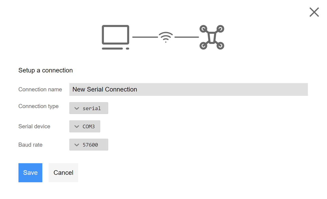
On the GCS computer, the user has to establish the serial connection by filling in the following details.
- Connection Type: Serial
- Serial Device: The COM port the telemetry is connected to on the GCS computer.
- Baud Rate: The baud rate of the telemetry module.
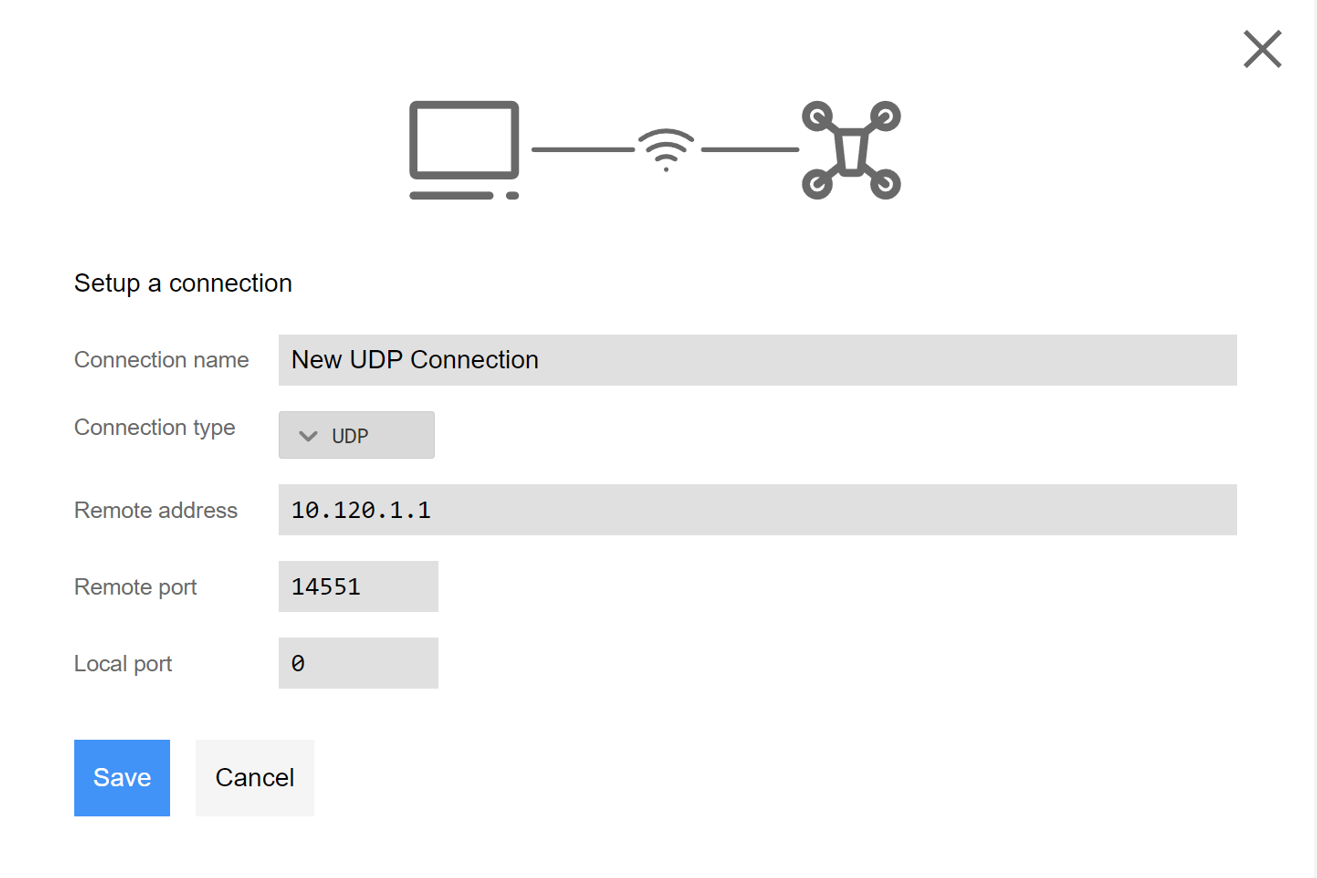
Connection over UDP
It is also possible to establish connection over UDP rather than the Serial Port. The default port for this UDP is 14551 and must be filled out in the settings of the web-interface GCS connection.
On the GCS computer, the user has to establish the UDP connection by filling in the following details.
- Connection Type: UDP
- Remote address: IP address of the Reflex as displayed in the web-interface, refer Connecting to the Reflex or the reflex host name such as reflex123. If the GCS computer is directly connected to reflex's wifi, this value would be 10.120.1.1.
- Remote Port: By deafult it is 14551.
- Local Port: Should be kept at 0, the value is automatically configured.
Web Interface: Settings > MAVlink > GCS Connection
Battery Monitoring
Drones are often flown using Lithium Polymer (LiPo) batteries. Depending on the size of the drone and the current drawn by the components, different kinds of LiPo batteries are used. Their variation often comes in regards with the number of cells used in the battery as well as its capacity.
However, there are characteristics of a battery cell which can be taken as constant as well as the thresholds depending on when failsafes, warnings or stops must be triggered. The commonly used values for these are given in the table below. These are the recommended values and any changes made to them would be at a user's discretion.
| Setting | Value (V) |
|---|---|
| Max Cell Voltage | 4.2 |
| Low Cell Voltage | 3.7 |
| Critical Cell Voltage | 3.55 |
| Emergency Cell Voltage | 3.2 |
These values must be filled out under the appropriate settings by navigating to Battery as given below.
Web Interface: Settings > System Monitor > Battery
Under these settings, the user can also fill out the number of cells used in the battery to power the drone.
Calibration
The voltage and current multipliers are necessary for converting the analog inputs from the power module to actual measurements. These multipliers are usually provided in the specification sheet of the power module as voltage and current dividers. However, if they are not specified, they can be calculated as follows.
\[ V_{multiplier} = \frac{Max\ voltage\ of\ power\ module}{power\ module\ analog\ signal\ range} \]
For example, if a power module has a maximum voltage rating of 60V and sends an analog signal in the range of 0-3.3V. The voltage multiplier would be 18.18. The resulting \( V_{multiplier }\) should be filled in the Settings.
Since correct battery voltage monitoring is essential for battery failsafe modes, it is advised that the voltage multiplier is calibrated by hand using a multimeter:
Measure the battery voltage using a multimeter. This value is called \( V_{measured}\). Check the battery voltage in the web interface. This value is called \( V\). If \( V_{measured}\) is not equal to \( V\), update the \( V_{multiplier }\) value with the following formula:
\[ V_{multiplier} = \frac{ V_{measured}}{V} * V_{multiplier_{prev}} \]
The procedure for the \( I_{muliplier} \) computation is similar and is an optional value.
Basic Configuration
This chapter covers the essential configuration needed to enable manual flight modes and get your drone in the air.
Remote COntroller
Channel Mapping
- Pilot Sticks:
The channel mapping for controlling roll, pitch, throttle, and yaw can be configured here.
Web Interface: Settings > Commander > Remote Controller > Channel Mapping > Pilot Sticks
- Flight Mode Switch 1:
The flight mode selection function for the first switch should be configured with a channel corresponding to a three-way switch.
- Low (Negative position)
- Centre (Zero position)
- High (Positive position)
The flight mode corresponding to the active position of this switch is considered as the initial mode upon arming. If the current position of switch 1 is not assigned to a mode, the flight mode corresponding to switch 2's active position is used.
Web Interface: Settings > Commander > Remote Controller > Channel Mapping > Flight Mode Switch 1
- Flight Mode Switch 2:
The flight mode selection function for the second switch should be configured with a channel corresponding to a three-way switch.
- Low (Negative position)
- Centre (Zero position)
- High (Positive position)
Web Interface: Settings > Commander > Remote Controller > Channel Mapping > Flight Mode Switch 2
- Arm Switch:
The arm switch configuration is detailed in this section. It can be mapped to either a two-way or a three-way switch.
- Positive: Arm.
- Negative / Zero: Disarm.
Web Interface: Settings > Commander > Remote Controller > Channel Mapping > Arm Switch
- Kill Switch:
The configuration for the kill switch, which forcefully shuts off the input signal to the motors, can be found here. It can be mapped to either a two-way or a three-way switch.
- Positive: Kill disabled.
- Negative / Zero: Kill enabled.
To be able to arm the drone, the kill switch has to be disabled.
Web Interface: Settings > Commander > Remote Controller > Channel Mapping > Kill Switch
- Algorithm Switch:
This switch is used to select the desired control algorithm between PID and INDI. It can be mapped to either a two-way or a three-way switch.
- Positive: INDI.
- Negative / Zero: PID.
Web Interface: Settings > Commander > Remote Controller > Channel Mapping > Algorithm Switch
Stick Limits
- Upward Throttle Limits:
These settings define the minimum and maximum throttle values mapped to the throttle stick.
Web Interface: Settings > Commander > Remote Controller > Upwards Throttle Limits
- Bank Angle Limit:
The maximum bank angle limit is defined here, allowing users to set limitations on how much the drone may bank during flight for full stick deflection. This setting helps maintain stability and control during maneuvers.
Web Interface: Settings > Commander > Remote Controller > Bank Angle Limit
- Yaw Rate Limit:
This parameter determines the maximum rate of rotation around the vertical axis (yaw) for the drone for full stick deflection.
Web Interface: Settings > Commander > Remote Controller > Yaw Rate Limit
- Vertical Velocity Limits:
These settings define the minimum and maximum vertical velocities achievable by the drone during ascent and descent for full stick deflections. Adjusting these values can affect the drone's climbing and descending speeds.
Web Interface: Settings > Commander > Remote Controller > Vertical Velocity Limits
- Horizontal Velocity Limits:
Here, users can define the maximum horizontal velocity that the drone can achieve during lateral movements for full stick deflection. Controlling horizontal velocity allows for smooth and controlled flight.
Web Interface: Settings > Commander > Remote Controller > Horizontal Velocity Limits
- Deadzone: The deadzone area setting allows users to set a range in which small stick movements on the remote controller have no effect on the drone's movement. This helps prevent unintentional responses to minor stick inputs.
Web Interface: Settings > Commander > Remote Controller > Deadzone
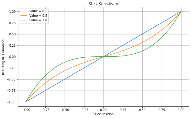
Stick Sensitivity
Stick sensitivity refers to the degree of responsiveness exhibited by the remote controller's sticks, particularly the pitch, roll, yaw, and throttle inputs. It determines how the drone reacts to your control inputs and affects the drone's agility and maneuverability.
In the Reflex, stick sensitivity can often be adjusted through the web-interface, enabling you to fine-tune the controls to suit your flying style and requirements.
Web Interface: Settings > Commander > Remote Controller > Stick Sensitivity
To make stick sensitivity adjustments effective for the throttle stick, it's essential to configure the hover throttle setting. This setting determines the throttle level at which the drone remains in a stable hovering position. Refer Hover Characteristics
Web Interface: Settings > Commander > Hover Characteristics > Hover Throttle
Velocity Smoothing:
For flight modes that rely on roll and pitch stick inputs to command velocity, it's feasible to refine the generated setpoint by implementing acceleration and jerk constraints on the stick commands. This approach enhances the precision and control of velocity adjustments during flight, resulting in smoother and more controlled movements.
Web Interface: Settings > Commander > Remote Controller > Smooth Velocity
Make small adjustments to the acceleration and jerk settings. If you're flying and notice that the drone's movements are too abrupt or jerky, reduce both acceleration and jerk slightly. On the other hand, if you feel the movements are sluggish or not responsive enough, increase these settings slightly.
Control Architecture
The Reflex supports a combination of PID and INDI control architectures. It is recommended to begin with configuring and tuning the PID controller as the INDI controller relies on certain parameters that need to be estimated from flight data. For detailed instructions on tuning each of the controller gains, please refer to the Tuning Guide.
Before configuring the INDI controller, ensure that all dependent settings for INDI are properly configured following the guidelines outlined in Configuring INDI. This step is crucial to optimize the performance of the INDI control algorithm and ensure smooth and stable flight operations.
PID Control Architecture
- Roll-Pitch Controller:
The Roll-Pitch controller is responsible for stabilizing the drone's roll and pitch angles. It consists of a P gain acting on attitude error and PID gains acting on velocity error. - Yaw Controller: The Yaw controller is responsible for stabilizing the drone's yaw angle. It consists of a P gain acting on attitude error and PID gains acting on velocity error.
- Vertical Controller:
The Vertical controller is responsible for maintaining the drone's desired altitude and velocity. It consists of a P gain acting on altitude error and PID gains acting on velocity error. - Horizontal Controller:
The Horizontal controller is responsible for maintaining the desired position and velocity. It consists of a P gain acting on position error and PID gains acting on velocity error.
INDI Control Architecture
- Roll-Pitch Controller:
The Roll-Pitch controller is responsible for stabilizing the drone's roll and pitch angles. It consists of a P gain acting on attitude error and PD gains acting on velocity error. The INDI control algorithm acts on the accelerations. - Yaw Controller: The Yaw controller in INDI controller is same as the one in the PID control architecture.
- Vertical Controller:
The Vertical controller is responsible for maintaining the drone's desired altitude and velocity. It consists of a P gain acting on altitude error and PD gains acting on velocity error. The INDI control algorithm acts on the accelerations. - Horizontal Controller:
The Horizontal controller is responsible for maintaining the desired position and velocity. It consists of a P gain acting on position error and PD gains acting on velocity error. The INDI control algorithm acts on the accelerations.
Piloted Flight Modes
Here, we will explore the essential sensors required and recommended for each flight mode and the controllers on which they depend. This will ensure that your drone performs optimally in various scenarios.
| Flight Mode | Required Sensors | Recommended Sensors |
|---|---|---|
| Attitude Mode | Reflex internal sensors | Range finder |
| Altitude Mode | Reflex internal sensors | GNSS (for precise altitude measurement), Range finder |
| Position Mode | Reflex internal sensors, GNSS positioning, GNSS Heading or Magnetometer | Range finder |
Each flight mode can operate with either PID or INDI control architecture. The dependencies of each flight mode on different controllers are as follows:
| Flight Mode | Controllers Used (PID/ INDI) |
|---|---|
| Attitude Mode | - Roll-Pitch Controller |
| - Yaw Controller | |
| Altitude Mode | - Roll-Pitch Controller |
| - Yaw Controller | |
| - Vertical Controller | |
| Position Mode | - Roll-Pitch Controller |
| - Yaw Controller | |
| - Vertical Controller | |
| - Horizontal Controller |
Failsafes
When flying a drone, it is important to ensure the safety of it as well as its surrounding environment. The flight controller is designed to detect when the drone encounters a problem or malfunctions and control the drone appropriately in response to this emergency. The failsafe modes can be configured for RC loss, battery exhaustion and geofence breach.
Failsafe Actions
Each failsafe action can be configured as the response per trigger by navigating to the relevant page as given below:
Web Interface: Settings > Commander > Failsafe
-
Land: When a failsafe is triggered and this option is chosen as the failsafe action, the drone lands in a controlled manner, starting from its current flying position.
-
Return to Home and Land: If triggered, the failsafe action leads the drone to return to its identified home position, usually where it was armed. Upon triggering, the drone first climbs or descends to the configured return altitude, then flies back to the home position while maintaining this altitude. The return altitude can be configured under the RTL section of the settings.
-
Kill: It causes the drone to be killed immediately upon a failsafe being triggered by stopping all the motors. This action is typically given the lowest priority during the configuration of failsafes and is only allowed for RC Loss trigger.
Failsafe Triggers
RC Loss
RC loss is considered to occur when the connection between the drone and the RC stops working during any flight and the pilot has no control of the drone. In this scenario, the drone must be safely brought to the ground. In case this failsafe is triggered, the drone can be configured to Land, RTL or Kill.
Battery Exhaustion
The low, critical, and emergency battery levels are defined by navigating in the web interface as seen below. Different actions take place at different battery levels.
Web Interface: Settings > System Monitor > Battery
When low battery level is reached, the drone is not allowed to arm until the battery is above this level once more. Additionally, the Dashboard of the web interface shows a warning indicating low battery level.
If the critical battery level is reached while flying, the drone's failsafe is triggered and one of the configured failsafe action is performed.
If the emergency battery level is reached while flying, the drone will immediately enter a failsafe land mode. This will cause the drone to land at its current lateral position, regardless of the configured failsafe action.
Geofence Breach
Geofences in the Reflex are defined by a cylindrical space in three dimensions. The height and radius of this cylinder can be configured in the settings. Following this, the failsafe action can be chosen as either the Land function or the RTL function. If the drone then breaches this geofence by crossing its boundaries, the failsafe would be triggered and, the chosen failsafe action would be carried out.
Web Interface: Settings > Commander > Failsafe > GeoFencing
Take-off Attitude
A takeoff attitude failsafe may be configured so that if the Reflex detects aggressive attitude changes during takeoff (which could be due to faulty configuration), the Reflex will automatically kill the motors for safety reasons. This can be configured here:
Web Interface: Settings > Commander > Failsafe > Takeoff Attitude Failsafe
Hover Characteristics
Hover Characteristics comprise of two key components: Hover Throttle and Hover RPM. To configure these settings accurately, a flight test involving hovering is necessary. During this test, observe the drone's behavior and record the mean RPM and mean throttle values from the flight log. Subsequently, input these mean values into the appropriate fields in the Settings. This process ensures that the Hover Characteristics settings align with the drone's actual performance, leading to enhanced stability and control during hovering maneuvers.
Web Interface: Settings > Commander > Hover Characteristics > Hover Throttle
Advanced Configuration
This section encompasses the following advanced configuration topics:
Tuning Guide
To ensure stable and responsive flight characteristics, proper tuning of the inner loop attitude controller and outer loop position controller is paramount. This guide aims to provide a systematic approach to tuning these controllers. When tuning the flight controller, it is crucial to follow a sequential order to ensure a systematic and effective tuning process. The recommended order of tuning is as follows:
- Roll-Pitch Controller:
The Roll-Pitch controller is responsible for stabilizing the vehicle's roll and pitch angles. For tuning the Roll-Pitch, it is recommended to use the Attitude mode. - Yaw Controller: The Yaw controller is responsible for stabilizing the vehicle's yaw angle. For tuning the Yaw controllers, it is recommended to use the Attitude mode.
- Vertical Controller:
The Vertical controller is responsible for maintaining the vehicle's desired altitude. When tuning the Vertical controller, it is advisable to use the Altitude mode. - Horizontal Controller:
The Horizontal controller is responsible for maintaining the desired position and velocity. For tuning the controller, Position mode has to be used.
Follow these steps for each sub-controller
- Initial Setup: Configure the controller with conservative gain values or use the default values to prevent aggressive control actions.
- Proportional Gain Adjustment: Gradually increase the proportional gain while observing the system's response. Monitor the system's behavior, responsiveness, and potential oscillations. Adjust the proportional gain until the desired level of responsiveness is achieved.
- Derivative Gain Incorporation: Introduce derivative gain to enhance the system's response to sudden changes. Evaluate the reduction of overshoot and the speed of stabilization. Fine-tune the derivative gain to optimize the system's behavior.
- Integral Gain Integration: Incorporate integral gain to address steady-state errors or biases. Analyze the system's response to long-term errors caused by disturbances or biases. Adjust the integral gain to minimize steady-state errors and ensure accurate and stable control.
Note: The tuning procedure for INDI controllers is similar to that of PID, except for the absence of an integrator.
INDI Control
To successfully operate the drone using the INDI controller, it's imperative to complete the following steps:
-
Ensure RPM Feedback: Verify the availability of RPM feedback through the Bidirectional DShot communication protocol.
-
Configure Motor Controller: Properly set up the Motor Controller, adjusting its parameters for accurate RPM control.
-
Set Hover Characteristics: Fill in the hover characteristics data, including hover throttle and hover RPM, to align with the drone's performance.
-
Tune INDI Controllers: Fine-tune the INDI controllers' gains and settings to achieve optimal performance and stability during flight.
By meticulously addressing these aspects, you'll establish the necessary conditions for utilizing the INDI controller effectively in your drone operations.
GNSS RTK
This manual provides step-by-step instructions for setting up a dual GNSS system with a fixed base for RTK, with a focus on heading applications. In this configuration, the fixed base station communicates RTK corrections to the moving base station via telemetry, while the moving base station sends RTCM messages to the rover over a wired connection.
It is important to highlight that this configuration is specifically designed for the u-blox F9P module. The steps and settings outlined in this manual may differ for other GNSS receiver models.
Additionally, it is worth noting that the same configuration can be applied in situations where a moving base is not utilized. In such cases, the RTCM messages from the fixed base station can be transmitted through the Ground Control Station (GCS) and the flight controller to the rover module. Additionally, telemetry modules can be used to send RTCM messages between Base station and the Rover.
To ensure a smooth and efficient configuration process, we strongly recommend using the u-blox u-center software. u-center provides a comprehensive and user-friendly interface specifically designed for u-blox GNSS modules.
Fixed Base Configuration
To configure the fixed base station for GNSS RTK, follow these steps:
-
Set the navigation rate on the base and rover to 8 Hz (125 ms) and the time source as UTC.
-
Configure UART1 on the base module to the telemetry baud rate, which is used for sending RTCM messages from the fixed base.
-
Enable the following RTCM messages on the base module by setting their values to 1:
- RTCM 1005: Stationary RTK reference station ARP
- RTCM 1074: GPS MSM4
- RTCM 1084: GLONASS MSM4
- RTCM 1094: Galileo MSM4
- RTCM 1124: BeiDou MSM4
- RTCM 1230: GLONASS code-phase biases
-
Perform a survey-in.
Moving Base Configuration
To configure the moving base for GNSS RTK, follow these steps:
-
Set the navigation rate on the base to 8 Hz (125 ms) and the time source as UTC.
-
Configure UART2 on the base module to 460800 baud, which is used for communication with the rover.
-
Configure UART1 on the base module to the telemetry baud rate, which is used for receiving RTCM messages from the fixed base.
-
Enable the following RTCM messages on the base module by setting their values to 1:
- RTCM 4072.0: Reference station PVT information
- RTCM 1077: GPS MSM7
- RTCM 1087: GLONASS MSM7
- RTCM 1097: Galileo MSM7
- RTCM 1127: BeiDou MSM7
- RTCM 1230: GLONASS code-phase biases
Rover Configuration
To configure the rover for GNSS RTK, follow these steps:
-
Set the navigation rate on the rover to 8 Hz (125 ms) and the time source as UTC.
-
Configure UART1 and UART2 on the rover to 460800 baud for communication.
-
Enable the following messages on the rover by setting their values to 1:
- UBX-NAV-RELPOSNED
- UBX-NAV-PVT
Note: The Reflex automatically configures the Rover module when connected to the GNSS port, while the base modules need to be manually configured.
Automated Maneuvers
The upcoming chapter provides an overview of the automated maneuvers supported by the Reflex flight controller. Prior to configuration, it is essential to ensure that the Reflex is properly configured and finely tuned in Position Mode. The flight maneuvers listed here are utilized by the automated flight modes and so, configuration of these maneuvers will impact the performance of the flight modes.
Automated Trajectories
Automated trajectories in the Reflex are used throughout other automated maneuvers to achieve jerk-limited flight between various waypoints. The trajectory settings will ultimately influence flight behaviour in the following maneuvers:
- Takeoff maneuver
- Land maneuver
- Return To Launch maneuver (RTL)
In order to configure the autonomous trajectories settings, please navigate to the following location.
Web Interface: Settings > Commander > Trajectory
Acceptance Distance:
When flying autonomous trajectories, the trajectory planner will consider a given waypoint to be reached when the drone's position and yaw are within the thresholds defined under Acceptance Distance. Once all thresholds are satisfied, the trajectory planner will begin to issue setpoints toward the next waypoint or end the trajectory if the final waypoint has been reached.
Web Interface: Settings > Commander > Trajectory > Acceptance Distance
Here, the user may define thresholds in terms of horizontal and vertical position along with yaw.
Max Bounds:
When generating a trajectory between waypoints, the system will ensure that the state of the vehicle does not exceed defined velocity, acceleration, and jerk limits. These limits can be configured in the following location.
Web Interface: Settings > Commander > Trajectory > Max Bounds
Here, bounds can be set independently for the horizontal, vertical, and yaw motions.
Takeoff Maneuver:
To configure the Takeoff maneuver, set the takeoff altitude in the settings. This value is relative to the home location. When executing the maneuver, if the drone's altitude is below the takeoff altitude, it will ascend to the takeoff altitude using an automated trajectory, otherwise it will hold its present altitude.
Web Interface: Settings > Commander > Takeoff Mode
Land Maneuver
There are two types of configurable landing maneuvers for the Reflex: Constant Speed and Smooth Touchdown. The Constant Speed maneuver is enabled by default and as the name suggests, the drone will descend with a configurable landing speed until touchdown.
Alternatively, the Smooth Touchdown maneuver may be selected which will prompt for the configuration of a landing speed, touchdown speed, touchdown height, and transition distance. In this configuration, the drone will descend at the defined landing speed until it reaches a height above ground (referred to as the transition height) which is equal to the sum of the touchdown height and the transition distance. Once it reaches the transition height, the commanded velocity setpoints will be linearly interpolated between the landing speed and the touchdown speed, such that when the drone reaches the touchdown height, its downward velocity will be equal to the touchdown speed. A depiction of this maneuver can be seen in the image below.
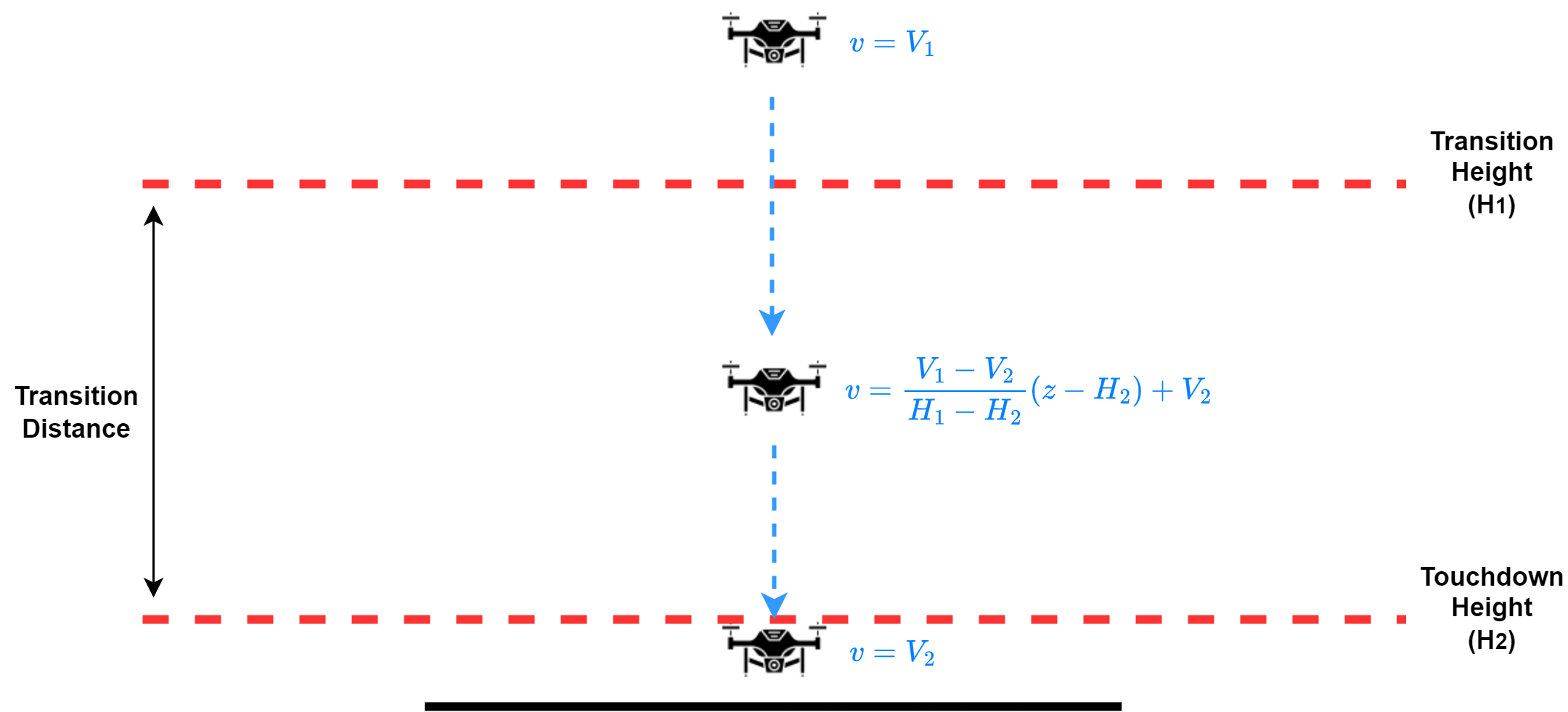
Note: The Smooth Touchdown landing maneuver relies on a height above ground estimate. If a Lidar is not configured or if Lidar measurements are lost during operation, the landing maneuver will issue a constant downward velocity setpoint equal to the landing speed for the entirety of the maneuver.
In addition to the above settings, there is an option named Autonomous Descent to Land Altitude. If enabled, the user must set a safe landing altitude at which the drone will begin its landing maneuver. If the drone's altitude is greater than the defined landing altitude, then it will descend using an autonomous trajectory until it reaches this point, at which it will commence the landing maneuver. If the drone is already below this altitude or if the option is disabled in the settings, the landing maneuver will commence immediately regardless of the drone's altitude. It is advised that this landing altitude is set to a value which is guaranteed to be above all potential obstacles in order to avoid collision during the autonomous trajectory.
The land maneuver settings can be found at the following location in the web interface:
Web Interface: Settings > Commander > Land Mode
RTL Maneuver
The Return To Launch (RTL) maneuver is used to automatically return the vehicle to its home location. This is done by first executing an automated trajectory to a position directly over the home location, followed by the execution of a land maneuver. The following defines parameters of the RTL maneuver which influence the altitude and the path which it takes during the automated trajectory phase.
Return Altitude:
The Return Altitude is the altitude to which the drone will climb before navigating back to the home position. This altitude is relative to the home altitude and can be configured in the settings.
Web Interface: Settings > RTL Mode > Return Altitude
Return above maximum reached altitude:
Additionally, there is an option to enable the drone to return at the maximum reached altitude since arming, if it is higher than the configured Return Altitude. This safety feature guarantees that the drone never returns at an altitude lower than the highest point it reached during the flight.
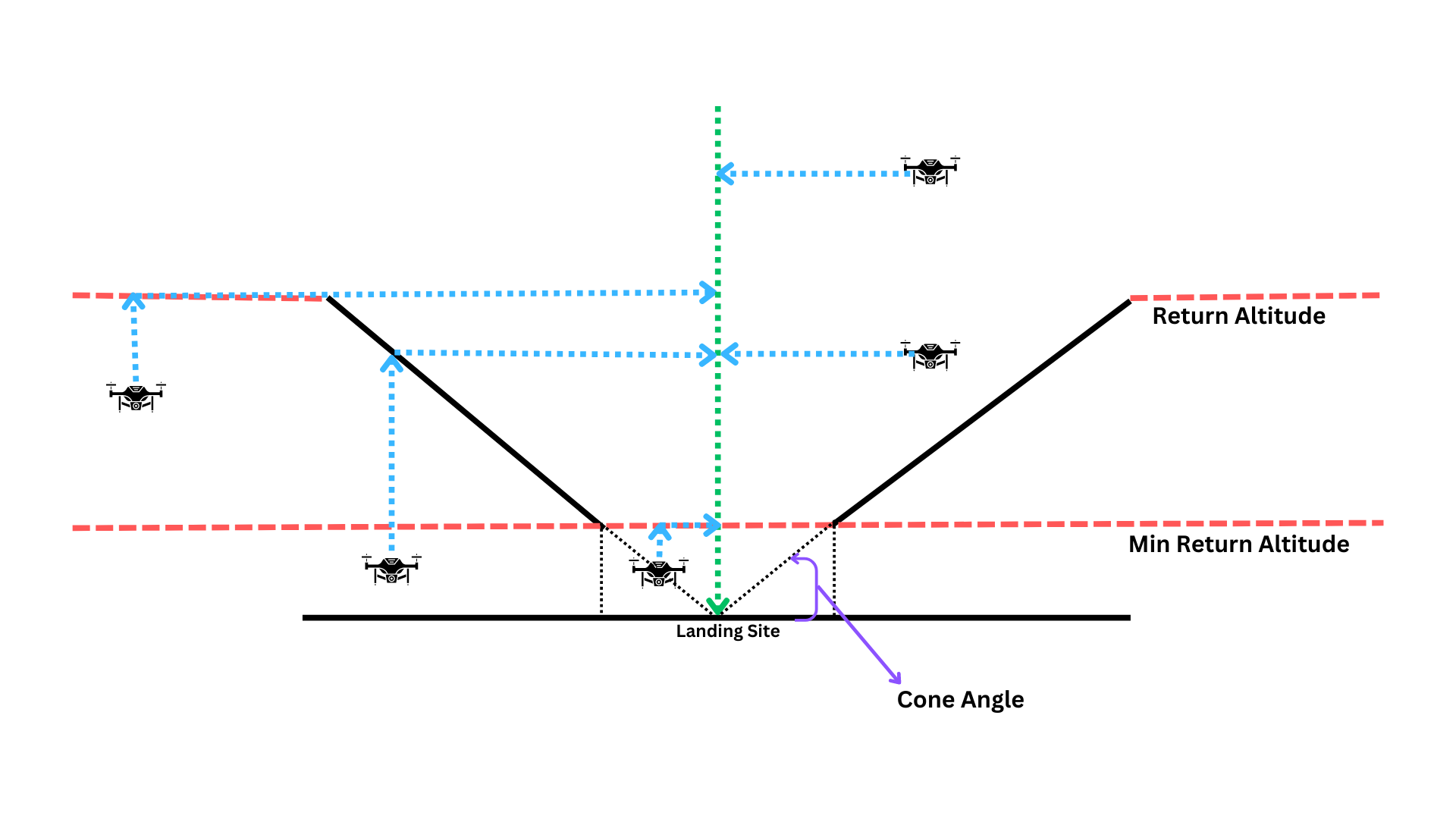
Altitude Coning:
In scenarios where there is an open area around the landing site, the drone can be configured to perform the return flight at a lower altitude. This open area can be defined as a cone extending above the landing site.
If the cone feature is enabled, the return sequence follows these steps:
- If the drone is below the Min Return Altitude, it will climb upwards to reach the Min Return Altitude.
- The drone will then climb to reach the configured Return Altitude or climb to enter the cone, whichever altitude is lower.
- Once it reaches the desired altitude, the drone will fly horizontally at this level towards the landing site.
- Finally, the drone will execute a controlled landing.
This configuration is especially useful for the RTL (Return to Launch) mode, ensuring safe and efficient return operations for the drone.
State Estimator
The Reflex employs an Unscented Kalman Filter (UKF) for determining the state of the drone based on various sensor inputs. The following section outlines the configuration of the various sensors that influence the state estimator.
Sensor Selection
Here, users can configure which sensors to use for different state estimations.
Heading
Users have the flexibility to choose between a magnetometer-based setup or a dual GNSS setup for heading estimation.
For selecting the heading estimation method, please navigate to the following location:
Web Interface: Settings > State Estimator > Sensor Selection > Heading
If GNSS heading is chosen as the heading estimation method, it's essential to configure the GNSS heading setup:
Web Interface: Settings > State Estimator > GNSS > GNSS Heading Setup
Note: If Mocap is used for position estimation, heading is automatically derived from the Mocap data.
Position
The Reflex supports both motion capture systems and GNSS for position estimation. The user may select the desired position source here:
Web Interface: Settings > State Estimator > Sensor Selection > Position
Advanced Features
The following section provides and overview of the Reflex's advanced features along with how they can each be configured. These features may be enabled to improve flying quality.
Takeoff and Landing Detection
This feature enables the Reflex to detect the takeoff and landing states of the drone, allowing it to perform actions like disarming due to takeoff timeout and after landing.
To ensure the effectiveness of this feature, there are limitations on the maximum bank angle when the drone is close to the ground. These limitations include:
-
Touchdown Height: Below this height from the ground, the bank angle is constrained to zero.
-
Coning Distance: Above the touchdown height, there is a coning distance within which the maximum allowable bank angle setpoint gradually scales down to zero from maximum bank angle until it reaches the touchdown height.
The pilot regains full bank control authority above the touchdown height plus the coning distance.
Additionally, the feature restricts horizontal forces and throttle when the drone is on the ground before takeoff and after landing.
For optimal performance of this feature, it is recommended to enable the bank angle limitation and the associated actions.
To enable auto-disarm on landing, ensure the throttle stick is fully down in piloted modes, and avoid any horizontal movement commanded by the pilot. In automated modes, no additional pilot intervention is required for auto-disarm.
Web Interface: Settings > Commander > Takeoff And Landing Detection
RPM Notch Filter
The RPM notch filter aims to minimize noise picked up by the flight controller's internal IMUs that is caused by vibrations from the rotors. This feature allows the user to configure a set of notch filters whose centre frequencies will dynamically change to attenuate the frequencies of each of the motors.
Note: This feature relies on feedback of the motor RPMs and thus is only functional when the Bidirectional DShot protocol is being used.
To enable and configure the RPM notch filter, navigate to the following location from the web interface:
Web Interface: Settings > Internal Sensors > IMU RPM Notch Filter
Here, the following parameters need to be configured:
- Bandwidth: The frequency range around each notch filter's centre frequency which should be attenuated.
- Minimum Frequency: The lower bound of frequencies which should be attenuated by the notch filters. If the measured motor frequencies are below this value, then the data will not be filtered.
- Fade Range: The range of frequencies above the Minimum Frequency during which the filter effect is linearly faded in/out. For example, if the Minimum Frequency is set to 30Hz and the fade range is set to 10Hz, then the filters have no effect at 30Hz and linearly increase in effectiveness until they are fully effective at 40Hz. The purpose of this is to avoid sudden changes in computation of the filters, which could lead to numerical instability.
- Number of Harmonics: The feature can also be configured to filter out the first three harmonics of the motor frequencies to account for noise induced by the propellers. It is recommended that the number of harmonics chosen to be filtered corresponds to the number of blades on the propellers. For example, if using three bladed propellers, it is best to set the number of harmonics to three.
Flight Operations
This section provides instructions on arming and changing flight modes, conducting missions, and covers all the essential information you need to know to operate the drone effectively in the field.
Pre-Arm Checks
The Reflex implements a series of pre-flight checks to ensure the drone is in a safe state to arm and fly. These checks include:
-
Throttle Stick Down: The throttle stick must be in the down position, indicating a zero throttle input.
-
Drone Standing Still: The drone should be stationary on the ground, ensuring that it is not in motion before arming.
-
Drone Upright: The drone must be in an upright position, with its orientation aligned properly.
-
Battery Level Above Critical: The battery level needs to be above the 'Low Cell Voltage', ensuring sufficient power for safe flight.
-
Gyro and Accelerometer Check: The gyroscope and accelerometer sensors are checked to ensure they are functioning correctly.
-
State Estimator Running: The state estimator, responsible for estimating the drone's position and attitude, is verified to be running properly.
-
Kill Switch Not Active: The kill switch on the RC (Remote Control) should be turned off to enable normal flight operations.
Arming, Disarming, and Mode Selection
This chapter provides detailed instructions for arming and disarming your drone, as well as selecting different flight modes.
Arming the Drone
To arm the drone, follow these steps:
- Ensure that the drone is in a safe and suitable location for takeoff.
- Verify that the "arming allowed" status is displayed on the web-interface dashboard.
- Move the arm/disarm switch to the "arm" position to successfully arm the drone.
Disarming the Drone
To manually disarm the drone, follow these steps:
- Ensure that the drone is in a safe and controlled state to disarm.
- Move the arm/disarm switch to the "disarm" position while holding the throttle stick down.
If the takeoff and landing detector is configured to auto-disarm, the drone will auto-disarm upon landing. In piloted modes, auto-disarm requires the throttle stick to be fully down.
Flight Mode Selection
Refer to the flight mode's documentation to understand the available flight modes and their respective functionalities.
Flight mode selection depends on the configuration of two switches: Switch 1 and Switch 2, each with three positions.
During arming, the flight mode mapped to Switch 1's current position is considered the active mode. If the current position of Switch 1 is not mapped to any mode, the flight mode mapped to the position of Switch 2 is used as the current flight mode.
While in flight, the flight mode corresponding to the switch movement is considered. Moving a specific switch will activate the flight mode associated with that switch's movement.
Currently, the only way to change modes is through the flight mode switches.
Missions
This document provides an overview for defining autonomous missions either directly from the Reflex's web interface or from the Ground Control Station (GCS). A mission consists of an optional autonomous takeoff, followed by an autonomous trajectory between user-defined waypoints, and finally an optional autonomous landing. The trajectory flown between the defined waypoints will be generated with respect to the Trajectory Settings.
A mission can be easily configured through either the Reflex's Web Interface or the Ground Control Station (GCS).
Missions From Web Interface:
Mission elements can be configured from the web interface by navigating to the following settings:
Web Interface: Settings > Trajectory
Takeoff & Landing
Here, the user may enable autonomous takeoff at the beginning of the mission by selecting the Takeoff checkbox and entering the desired takeoff altitude relative to the home position. Similarly, an autonomous landing at the completion of the mission may be enabled by selecting the Landing checkbox. The Reflex will use the landing speed from the land maneuver settings.
Waypoints
Setting waypoints can also be done from the same settings section. The Reflex flight controller will plan jerk-limited trajectories between each of the defined waypoints as per the configuration set in the Trajectory Settings. Under the Waypoints header in the mission settings, select Add to append a waypoint to the mission. Once added, the user may include optional waypoint definitions for its Horizontal Position, Height, Yaw, and Hold Time.
When defining a waypoint's horizontal position, an option is provided to define the coordinate in either a Global or Local ENU frame of reference. If Global is selected, then the user may define the waypoint location relative to the Geographic Coordinate System in terms of latitude and longitude. Otherwise, if Local ENU is selected, then the waypoint location is defined as its distance from the origin in metres East and North.
As previously mentioned, the yaw angle of the drone at the waypoint can also be configured. It is set in terms of degrees from the East axis (i.e. East: 0°, North: 90°, West: 180°, South: 270°).
If a hold time is included for a waypoint, then the drone will be commanded to fly to the waypoint, come to a stop, and hold its position for the specified time until continuing to the subsequent waypoint.
Missions From GCS:
Alternatively, missions may also be configured directly from the GCS. To do so, using the navigation bar at the top of the application, select Missions. This will open up a side-panel in which the user may create a new mission or load an existing one.
Takeoff & Landing
Once a mission has been created, the side-panel will show both the takeoff and land mission items as disabled. Select either checkbox to enable either item. Selecting the drop-down arrow next to the takeoff checkbox will allow the user to enter the desired takeoff altitude, similar to in the web interface.
Waypoints
Waypoints may be configured in the GCS using one of two methods. The easiest way to add a waypoint is to simply right-click the location on the map which the drone is to fly to. This will bring up the option to add a waypoint. Once the waypoint is added, it will appear in the mission side-panel. Selecting the corresponding drop-down arrow will display the waypoint configuration menu where its position, altitude, heading, and hold time can all be adjusted. Alternatively, a waypoint may be added by selecting Add step > Waypoint from the bottom of the side-panel. This will add a default waypoint to the mission.
A return to launch item may also be added by selecting Add step > Return from the bottom of the side-panel. This will instruct the drone to return back to its home location.
Flight Log Analysis
This chapter provides valuable insights into the data logging capabilities of the Reflex. The Reflex automatically records essential flight data from the moment of arming until the drone is disarmed. This data is logged in a custom dlog format, enabling users to review and analyze flight details and performance.
-
Accessing Flight Logs: The recorded logs can be viewed in the Reflex Web interface under the Logs section. To access the logs:
- Launch the Web interface.
- Navigate to the Logs page.
- Click on the Plot icon to open the dlog viewer in a new tab.
-
Analyzing Flight Logs:
- Use the dlog viewer to visualize and interpret the recorded flight logs.
-
Exporting Flight Logs:
- On the Logs page of the Reflex Web interface, you can export the flight logs to CSV format by clicking on the CSV button next to the log file.
- Exporting the logs to CSV allows for further analysis using external tools or software.
Flight Parameters
This section provides guidance on where to locate essential flight parameters within the dlog file when using the dlog plotter.
- States
- Position ENU (m):
advanced-state-estimate/position - Velocity ENU (m/s):
advanced-state-estimate/velocity_enu - Euler angles (degree)
- Roll angle:
advanced-state-estimate/roll_deg - Pitch angle:
advanced-state-estimate/pitch_deg - Yaw angle:
advanced-state-estimate/yaw_deg
- Roll angle:
- Angular velocity filtered (rad/s):
commander-status/attitude_state_lpf/velocity - Acceleration ENU (m/s2):
advanced-state-estiamte/acceleration_enu - Height above ground (m):
advanced-state-estimate/height_above_ground
- Position ENU (m):
- Setpoints
- Position ENU setpoint (m):
commander_status/position_sp - Velocity ENU setpoint (m/s):
commander_status/velocity_enu_sp - Euler angles setpoint (degree)
- Roll angle setpoint:
commander_status/roll_deg_sp - Pitch angle setpoint:
commander_status/pitch_deg_sp - Yaw angle setpoint:
commander_status/yaw_deg_sp
- Roll angle setpoint:
- Angular velocity setpoint (rad/s):
commander_status/angular_velocity_sp
- Position ENU setpoint (m):
- Mean throttle:
commander_status/mean_throttle - Flight mode:
commander_status/flight_control/flight_mode- 0 = Attitude
- 1 = Altitude
- 2 = Position
- 3 = Mission
- 4 = Failsafe RTL
- 5 = Failsafe land
- 6 = Kill
- 7 = Land
- 8 = Hold
- 9 = Takeoff
- 10 = RTL
- Position source:
advance-state-estimate/position_source- 0 = GNSS
- 1 = Mocap
- Heading source:
advance-state-estimate/heading_source- 0 = Magnetometer
- 1 = GNSS
- 2 = Motion Capture
- Control algorithm:
commander_status/active_control_algorithm- 0 = Feedforward
- 1 = PID
- 2 = INDI
- Takeoff and landing detection:
- Takeoff Detection :
commander_status/takeoff_and_landing_detection_result/takeoff_detector_result- 0 = Not configured
- 1 = Takeoff not detected
- 2 = Takeoff detected
- Landing Detection :
commander_status/takeoff_and_landing_detection_result/landing_phase- 0 = Not detected
- 1 = First Intermediate landing phase detected
- 2 = Second intermediate landing phase detected
- 3 = Landing detected
- Takeoff Detection :
- Motors
- Motor configured :
motors/motors/[ESC port number]/configured - RPM setpoint :
motors/motors/[ESC port number]/rpm_setpoint - RPM feedback :
motors/motors/[ESC port number]/rpm_feedback - Throttle setpoint :
motors/motors/[ESC port number]/throttle_setpoint
- Motor configured :
- Remote control
- Raw channel data:
rc - Commander processed RC data:
rc_status
- Raw channel data:
- Raw sensor data
- IMU:
sensors/accgyr - Barometer:
sensors/pressure - GNSS:
sensors/gnss - Range Finder:
sensors/distance - Magnetometer:
sensors/magneto
- IMU:
- Battery information:
power
Emergency Procedures
The Emergency Procedure section of the documentation provides essential guidelines and instructions to handle critical situations related to sensor failure and unexpected flight behavior. In this chapter, you will learn how to effectively respond to these scenarios to ensure the safety and stability of your drone operations.
Sensor Failure Handling
In the event of a sensor failure, the flight controller is designed to automatically take appropriate actions to ensure the system continues to operate safely and effectively. The following table outlines the automatic actions performed by the flight controller for different sensor failures:
| Sensor Lost | Automatic Action |
|---|---|
| GNSS | Shift to Altitude mode |
| Magneto/GNSS Heading | Shift to Altitude mode |
| Range Sensor | Reduced feature availability |
-
GNSS Failure: If the GNSS signal is lost in Position or Automated Modes, the flight controller will automatically shift the system to altitude mode. This allows the system to rely on other sensors and maintain stable flight without positioning.
-
Magneto/GNSS Heading Failure: In the event of a failure in the magnetometer or GNSS heading Position or Automated Modes, the flight controller will automatically shift the system to altitude mode. This ensures that the system can still maintain its altitude and stability without relying on the heading information from these sensors.
-
Range Sensor Failure: When the range sensor encounters a failure, the flight controller will automatically reduce certain features or functionalities, such as terrrain hold and bank angle limit close to ground, that rely on range data. It is important to note that some features may not be available or may be limited due to the absence of range information.
Unexpected Flight Behaviour
If you encounter unexpected behaviour with the Reflex flight controller, follow these steps to regain control:
-
Centralize Controls: Centre the throttle, yaw, and pitch/roll sticks to their default positions.
-
Observe the Drone: After centring the controls, carefully observe the drone's behavior. If it continues to fly in an uncommanded manner in either Automated or Position Mode, proceed to the next step.
-
Switch to Altitude Mode: If the unexpected behaviour persists in Automated or Position Mode, switch the flight controller to Altitude Mode. This mode maintains the drone's altitude but removes the position control functionality. It allows you to regain control and stabilize the drone.
-
Assess the Situation: Once in Altitude Mode, evaluate the drone's behaviour and determine if it has stabilized. If the drone is under control and responding correctly, you can proceed with normal flight operations. However, if the unexpected behaviour persists or worsens, proceed to the next step.
-
Switch to Attitude Mode and Land: If the drone is still exhibiting uncommanded behaviour in Altitude Mode, switch the flight controller to Attitude Mode. This mode provides manual control of the drone's attitude (pitch, roll, and yaw) without relying on external sensors or positioning systems. Use Attitude Mode to stabilize the drone and land.
-
Identify Possible Causes: Unexpected behaviour can be caused by various factors such as erroneous sensor readings, degraded GPS signal reception, or compass issues. Take note of any potential factors that could have contributed to the unexpected behaviour for further troubleshooting.
Software Updates
Since the Fusion Reflex is still under active development, software updates will be available reguarly with improvements and new features.
There are two ways to update the software on your Reflex.
Automatic Incremental Updates
Under Advanced → Manage Updates in the Web Interface, you can check for the availability of software updates, which can then be downloaded and installed automatically.
It's important to make sure the Reflex stays powered on through the entire update process. If power is lost while an update is in progress, the software or data on the Reflex is likely to be damaged and will require you to do a manual full system. Please contact us for the procedure.
Contact
If you require any support, need to report any software or documentation bugs, or would like to request a feature, please create a ticket using our Jira Service Desk.
If you don't have access to the service desk, please send an email to ea@fusion.engineering.